26.12.11

At last. Flexacopter

[quote=holco]New project for a Heavy-Lifter camera platform.
The objective are,
Multiple system use, such as, Mikrokopter with the V2.0 ESC's / OpenPilot / KKuk / and others.
Hexa setup, + and X mode.
5S setup with one 8000mAh lipo for long efficient flights.
Easy removable 20mm carbon arms with integrated power and led plugs for easy transportation in a custom case with foam padding.
Carbon 180mm frame and carbon supports for the Avroto 2814 short shaft motors.
Compact Wire Rope Isolators (diy) + gel dampers for max vibration damping.
Diy roll/tilt gimbal (AV-200 look alike).
Good looks!!
[img]http://www1.picturepush.com/photo/a/6719869/1024/Flexacopter/Unknown-1.png[/img]
[img]http://www3.picturepush.com/photo/a/6719881/1024/Flexacopter/Unknown-3.png[/img]
[img]http://www3.picturepush.com/photo/a/6719871/1024/Flexacopter/Unknown-2.png[/img]
Dimensions test for the MK V2.0 ESC's mounting holes,[img]http://www2.picturepush.com/photo/a/6722170/1024/Flexacopter/DSCF0024.jpg[/img]
Production of the Avroto supports in 2,5mm carbon,[img]http://www5.picturepush.com/photo/a/6722883/1024/Flexacopter/foto.jpg[/img]
[url]http://www.youtube.com/watch?v=QORE_zQUeZk[/url]
The results,[img]http://www5.picturepush.com/photo/a/6723138/1024/Flexacopter/PA094314.jpg[/img]
[img]http://www4.picturepush.com/photo/a/6723157/1024/Flexacopter/PA094327.jpg[/img]
[img]http://www5.picturepush.com/photo/a/6723173/1024/Flexacopter/PA094336.jpg[/img]
[img]http://www5.picturepush.com/photo/a/6723188/1024/Flexacopter/PA094338.jpg[/img]
[img]http://www2.picturepush.com/photo/a/6723205/1024/Flexacopter/PA094347.jpg[/img]
First test model of a diy Compact Wire Rope Isolator, tests show a vibration reduction of 70% with 500g load,[img]http://www1.picturepush.com/photo/a/6723334/1024/Flexacopter/PA094353.jpg[/img][/quote]

23.4.06

This is what i put my money on!

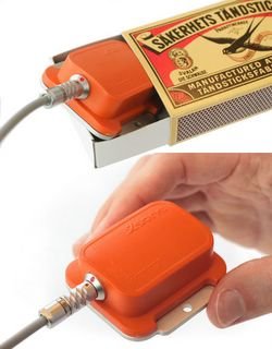
This is what i put my money on! After searching so long for a usable and affordable AHRS i found this. and guess what? Its made in Holland!


A miniature, real time, Attitude & Heading Reference System offering full 360 degree digital outputs of rate of turn, linear acceleration and heading.

MEMS gyros & accelerometers
Solid state magnetic compass
DSP modelling of drift and bias
High update rate
Temperature, 3D misalignment & cross axis compensated
Optional compass soft iron compensation
Development kit with software

These are the guys that make it. http://www.xsens.com/


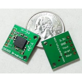
!! 2-Axisgyroscope in ONE bga! Waht about the third axis? Could they not have put it in ? Just kidding:)


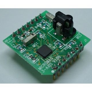
3-Axis magneto from sparkfun. This nice thingy could solve the problem of eulers, quaternions and .....

27.6.05


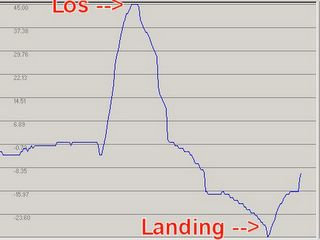
See the altitude difference between start and landing. Don't trust GPS altitude to much.


GPS receiver. Note the large backup battery. The receiver is the small metal box under the battery. The square thing on a wire is the active antenna.


Thats where it just fits.


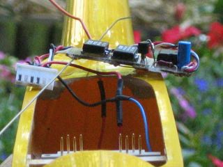
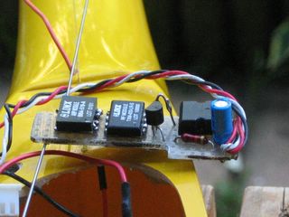
Linx LR tx and amp 3.3V regulator and inverting transistor to accept raw RS232 TX signal


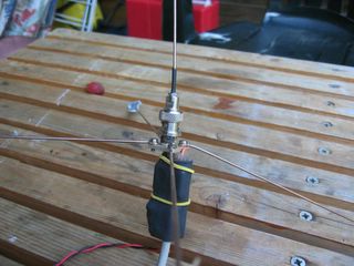
The 17cm groundplane antenna. In the schrinktube te Linx LR and Max232 Powered by one Lipo Cell it lasts for hours.

26.6.05

The first results

The first results are in. I just managed to get some online GPS data back to earth.

I build an 70cm (433Mhz) transmitter and receiver and put it all into my Sioux glider. Some successful 12 flights where logged using the donwlink.

For the downlink i used The LINX LR transmitter and reciever. (i will post some more photo's later.

Now i know the GPS and downlink works some autonomouse flight can be programmed.


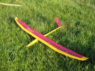
The testplane.


GPS data logged using my home build GPS and transmitter.

16.5.05


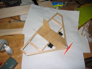
The beginning.


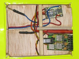
RX bay.


Servo's glued to rib and spar


Shulze RX and ESC


RC and battery ( 2s 350 LiPo )


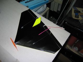
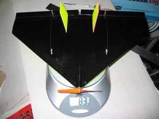
Here she is. Micro Diamond Dust.


12 INCH SPAN


Yes only 83 gram!

7.4.05


The Gyro and Accel test Posted by Hello

2.4.05

The first gadget.

I received an electronic compass. the CMPS03 from robot-electronics.co.uk look for the I2C compass module.

WOW they have some documentation and .... Sample programs :)

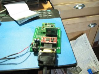
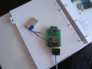
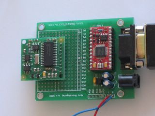
Connected the CMPS03 to the developmentboard put some wires on it so the ATOM can communicate using the I2C interface.

The setup

Closer
Quickly zapped the samplecode and imported it into the ATOM-Pro IDE.


SDA Con P8 ' Define Data pin
SCL Con P9 ' Define Clk pin
Compass Con 0xC0 ' Compass I2C Address
CmdReg Con 0 ' Compas Command register
BearingReg Con 2 ' Compas 1st Range register
Bearing Var Word ' 16 bit variable for Bearing
revision var byte ' revision of compass module

Serout S_OUT, i9600, ["Compass start", 13]
Main

pause 100
i2cin p8, p9, Err, 0xc0, 2, [Bearing.HighByte, Bearing.LowByte]

Serout S_OUT, i9600, ["Compass Bearing ", DEC Bearing/10, " graden", 13]

goto Main

Err

'Serout S_OUT, i9600, ["Compass error", 13]

goto Main


And .... I did not work! BUMMER. Some scoping showed a nice clock output, but no data-out on the data pin. Ok it was 3:00AM at that time so later we will look into the problem. After a good night sleep i woke up and remembered something i read in the renesas H8/3664 documentation about the ports on the micro. They need to be pulled up :) Glued a 10K resistor between the data-pin and VSS and whoopy :)


Note the damn pull-up resistor.

Finaly working communication. Yep i know RTFM.

Quickly zapped some code from some Swiss guys look here. The VB program was quickly adapted and see i have got my own electronic compass working.


TaDa...

Now the fun begins. the compass shows nicely how it is rotated in the horizontal plane. But tilted it shows eratic values. After discussing this with my dad he told met this problem with electronic compasses was first mentioned in the 50's duh! The Philips documentation below allso has some references to gimbaling. Not that i had a real purpose for the compass but it is a nice thingy.

The CMPS03 works with two Philips KMZ51 snsors. On the KMZ51 site there is a nice app-note for these sensors.

Hello World

The basics.

Run the ATOM-Pro IDE ( get it from www.basicmicro.com) and just slam in the code.


Out_Line VAR BYTE(20)
Out_Line = "Hello World", 10, 13, 0

loop
SEROUT S_OUT, I9600, [str Out_Line\13\0]
pause 1000
goto loop
end

To my surprise IT WORKS.........

Hello World
Hello World
Hello World
Hello World
Hello World
Hello World
Hello World
Hello World
Hello World
Hello World
Hello World
Hello World

To work.

As i have what, i think, i need to start experimenting. The work begins.

First of all i have to make a serial cable to connect the Basic Atom-24 Pro to my laptop.

A basic cable is all it takes.

DB9 female (PC) ......... DB9 male (Atom)
2 ---------------------------- 2
3 ---------------------------- 3
4 ---------------------------- 4
5 ---------------------------- 5


Power to the developmentboard by 2 serial LiPo cells (approx 8V) must be sufficient. The 78L05 on the board will take it down to 5V to power up the Atom.

Ready for takeoff.

1.4.05

Today an other happy day.

The final shipment of ordered goods arrived.
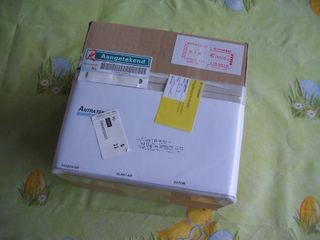
Again it was fun to unpack. More fun was to see that they shipped me three instead of two developmentboards :)


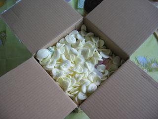
The box...


Sesame open!


The stuff.

23.3.05

Today a happy day.

Today i collected my first shipment of COTS components. After a long wait at the customs office a note from the postman told me i could pick up a shipment from the USA.

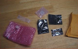
Today my GPS receiver and my MEMS (Gyro/Accel) boards arrived.

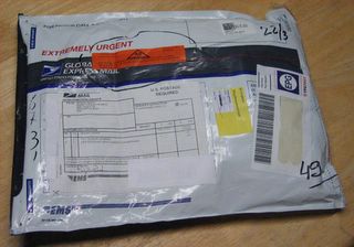
The unpacking.....


The envelope. 


The contents. 


Here it is. 

The process

There was an extensive selection, reading and discussion time before i ordered some components. As you can imagine i first browsed the web for an easy ready made and not to expensive solution. But $5000 for a hobbyist is a little expensive. I will discuss the components i ordered in detail as they arrive. A list of links will be posted to to show you all te information and manufacturers i found during my search for usefull information.